on
Office Christmas Tree: 3D Modelling
Once the lights were working I then needed some structure to put them in. The Christmas lighting community use many different materials, with corrugated plastic being a popular choice, but we have a 3D printer at the office so I decided to see what I could do with that.
The prototype
To get a rough idea of the size of the final shape and the number of lights I would use, I prototyped a Christmas tree shape with a piece of cardboard I had lying around.
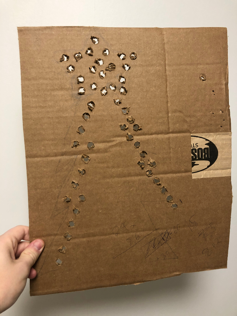
As you can probably see I started on the left with a spacing that I decided was going to be too big, making the distances shorter for the return leg.
Playing with Tinkercad
Once I had a rough idea of what I wanted I started looking around at 3D modelling software. The first one I tried was Tinkercad from Autodesk.
Tinkercad is an awesome peice of software for hobby projects, it’s easy to use and has a great online tutorial to help you get to grips with the basic controls.
It didn’t take long to get a very quick first draft together.
This was very rough around the edges but convinced me that I could achieve what I wanted to do.
For the next step I wanted to be sure that I was making holes that would fit the lights correctly so I created a testprint with three different diameters of hole.
Which came out looking like this
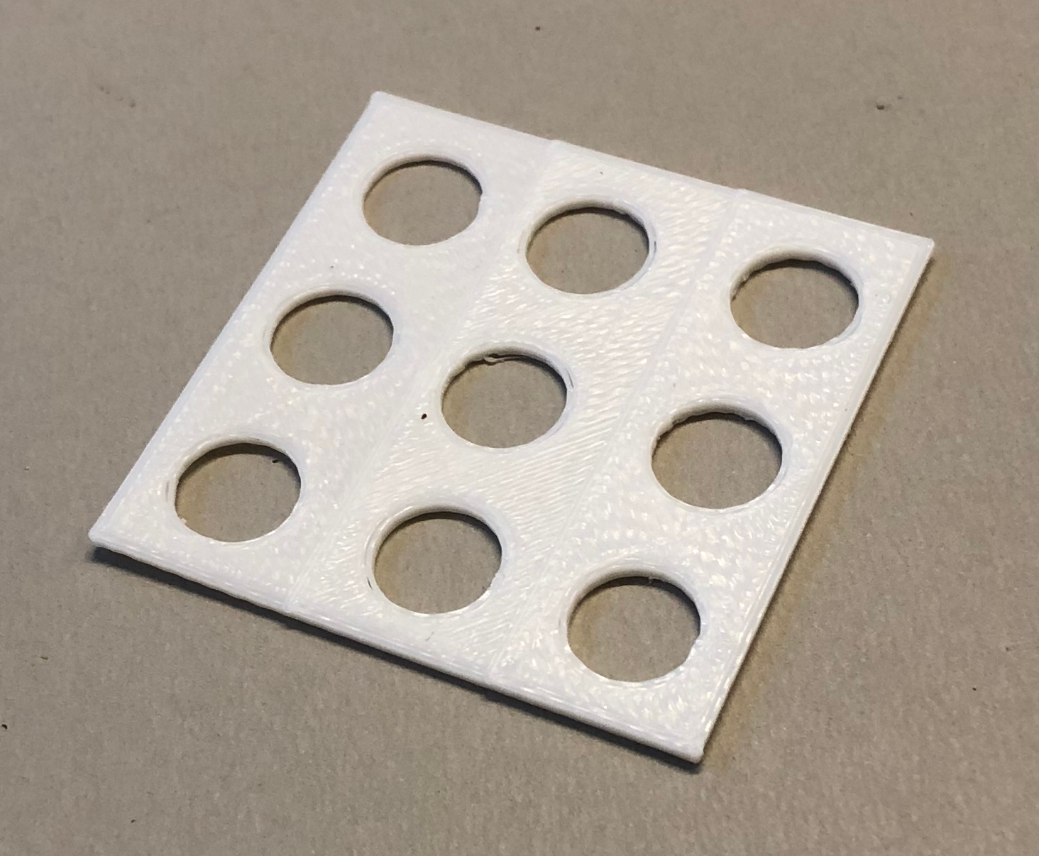
Testing with this plate, all of the holes worked ok but I realised that I could make the face of the Christmas tree thicker to give the lights more support.
After a couple of nights I ended up with the following design, the circles around the holes helped me to be certain that there was enough spacing between each light.
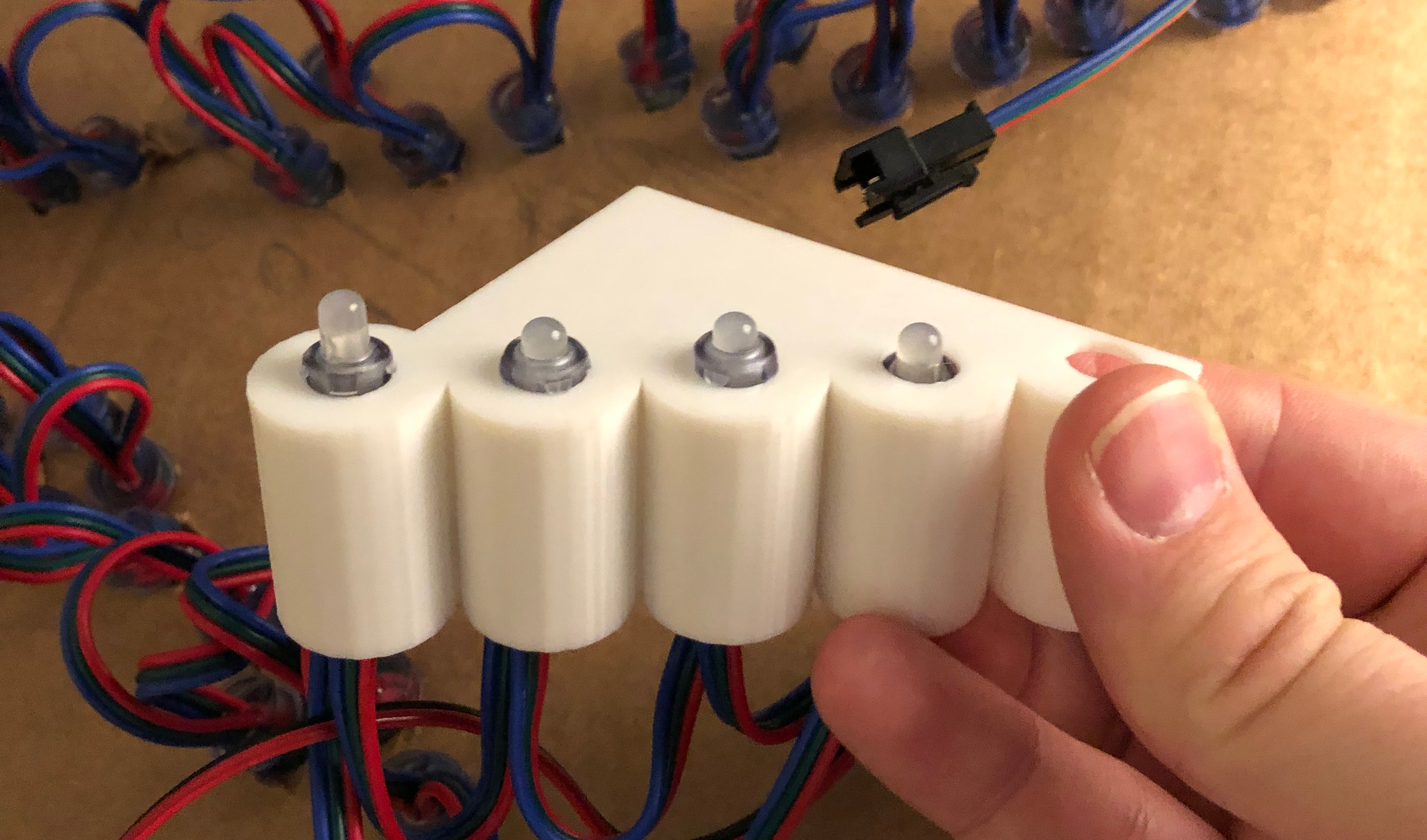
However a colleague recommended that I do a smaller test print before potentially wasting many hours on a test print. So for my first print I masked off most of the model.
This was a very good idea as it turns out, with the thicker front wall to the tree it wasn’t as easy to get bulbs in as my intial test print had suggested.
Looking at my model and how much effort I had put into positioning the holes in relation to each other, the tedious task of resizing everything wasn’t too appealing so I looked around to other solutions.
Enter OpenSCAD
Further googling lead me to OpenSCAD. Instead of a pretty drag and drop GUI, you “draw” models in OpenSCAD using a textual DSL which looks like the following.
  module bulbHole(x, y) {
    translate([x, y, -5]) cylinder_outer(40, 4.5, 20);
  }

  module holesForBranch(branchNumber) {
    translate([0, -branchYOffset(branchNumber), 0]) {
      for (bulbNumber = [1:baseNumberOfBulbs+branchNumber]) {
        bulbHole(xDistanceBetweenBulbs* bulbNumber + branchXOffset(branchNumber), -yDistanceBetweenBulbs * bulbNumber);
          bulbHole(-xDistanceBetweenBulbs* bulbNumber - branchXOffset(branchNumber), -yDistanceBetweenBulbs * bulbNumber);
        }
    }
  }
As I’m a programmer by day, this was a better match for my skills, and further small changes could be easily be parameterised through the use of variables. Creating a model in this way felt quite similar to the experience I have from using SVG.
One other thing that encouraged me to try this approach was the fact that the problem of undersized circular objects for 3D printing is linked to from the cyclinder documentaion.
If I recall correctly I used about two evenings on getting this model where I wanted it. The code isn’t pretty, there’s a few warts I’d like to remove but it does the job and I have other projects to spend my time on.
I’ve published this on Thingverse if anyone is interested.
The next step was then the long wait….
The result
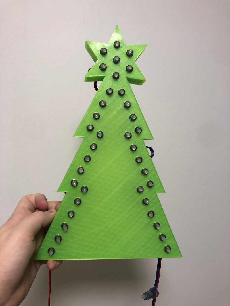
And so to the final result with the lights pushed snugly inn, perhaps a little too snugly, I’m not sure I could get them out without damaging the print, but why would I want to do that?
Next task to complete was to “sequence” the lights, I’ll dive into this in my next post.